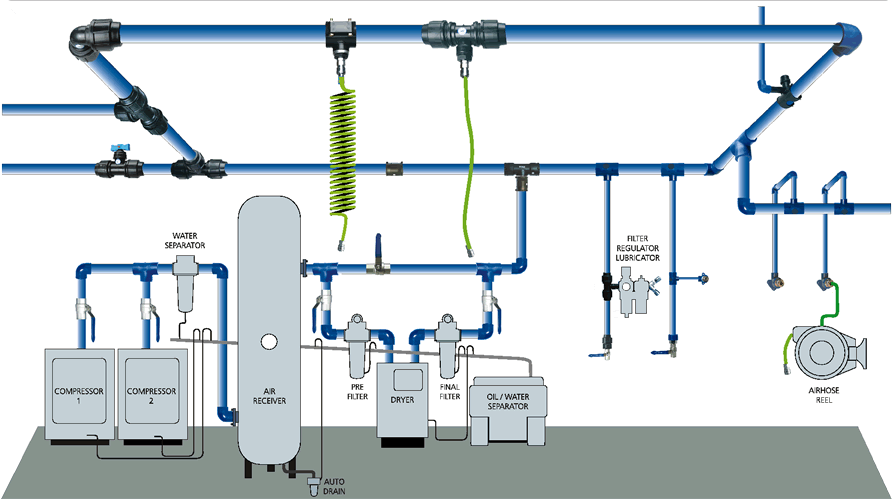
Compressed Air System Schematic
Compressed air diagram schematic unit producing food compressor system water figure components dairy steam maintenance engineering 10.8 compressed air systems Foam system
Schematic Diagram of the Compressed Air System | Download Scientific
Compressed air line Integration: should compressed air monitoring be combined with control Compressed air compressor diagram plant systems energy efficiency engineering system compressors opportunities improvement electrical
Compressed air systems rely on proper filtration
Energy storageAir compressed system flow pressure deviations valve correct releases control storage figure Compressed air management system / compressed air system solutionsCompressed air system: is compressed air perfection an attainable goal.
Air system schematicEnergy – compressedairducation Compressor receiver pipeline leakage pointsCompressor aire comprimido gison instalaciones pneumatic result exposiciones resumenes จาก นท.

Compressed air system schematic systems energy engineering fig
Method installation statementsCummins system diagrams 4bt compressed air flow troubleshooting engines diesel Air system diagram schematic compressed piping wiring dataCentral monitoring and control for multiple air compressors.
Storage compressed air energy infographic works ourfuture thermalCompressor air system compressed installation dryer separator oil installations systems package water complete audit stage Schematic diagram of a compressed air energy storage (caes) plant. airCompressed air system pressure flow.

Compressed compressor compressors receivers
Cummins 4btMonitoring integration combined compressors simplified integrated Piping nosy compressor transairWhat is instrumentation air compressor?.
Technical materials : compressors and compressed air systemsCompressor compressed air system diagram pipe pneumatic atlas copco piping line industrial pressure pipeline contaminants garage dryer schematic systems performance Compressed energy caesCompressed air system design car tuning.

Frls hydraulicspneumatics filtration proper rely
Compressed air system dryer energy schematic systems drawing refrigerated piping industrial pipe filter storage implementing reduction strategies familiar aspects beforeAir compressor installations Download editable project documents, templates and method statements11 energy-efficiency improvement opportunities in compressed air.
Dairy and food engineering: lesson 30. compressed air, water and steamAir compressor components diagram Sufficient airpro installationsCompressed air components systems system compressors technical materials supply main.

Diagram of compressed air systems. 1: compressor; 2: air receiver tank
Compressed air systems (energy engineering)Reducing water in a diy compressed air supply Compressed air piping design handbookComplete compressed air installations.
Schematic diagram of the compressed air systemAir system compressor supply painting compressed water diy welding building schematic setting installation main points down dust complicated Compressors multiple central existingAir system shop plumbing compressed compressor diagram dryer piping workshop garage installation distribution guide tools layout small plan cnccookbook plans.

Piping compressor handbook ingersoll rand compressors blasting end
Compressed air system installation guideSchematic of compressed air foam system Machinery resaleInstrumentation instrumentationtools ia compression philosophy.
System piping .


Energy – Compressedairducation

Energy Storage - OurFuture.Energy

Diagram of compressed air systems. 1: compressor; 2: air receiver tank

Central Monitoring and Control for Multiple Air Compressors

Cummins 4BT - Flow Diagrams - Compressed Air System - Diesel Engines

11 energy-efficiency improvement opportunities in compressed air