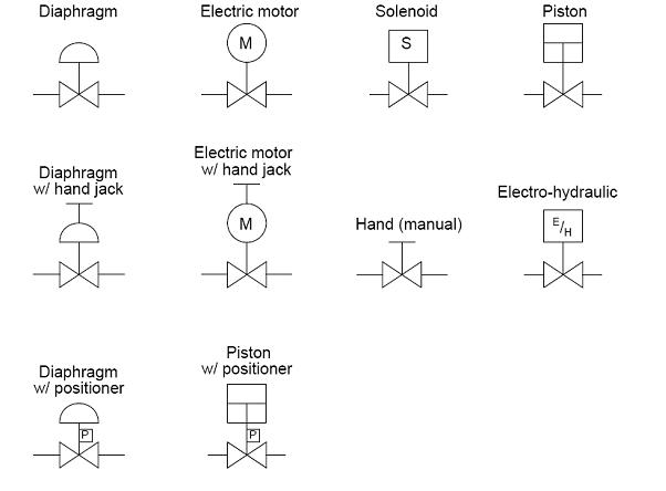
Flow Control Valve Schematic Symbol
Piping & instrumentation diagram, p&id – process flow systems P&id process diagram, piping, symbol, abbreviation, equipment, pump Pneumatic symbols circuit valve position explained solenoid spring return double flow actuated path
Hydraulic flow control valve symbols
Valve hydraulic control symbols directional symbol valves center closed position spring blocked four ports flow circuit pressure which between pdf Symbols valve solenoid valves drawing schematic symbol pid process diagram piping instrumentation developments connexion actuators control equipment represent used choose Flow control valve hydraulic pressure compensated schematic valves troubleshooting
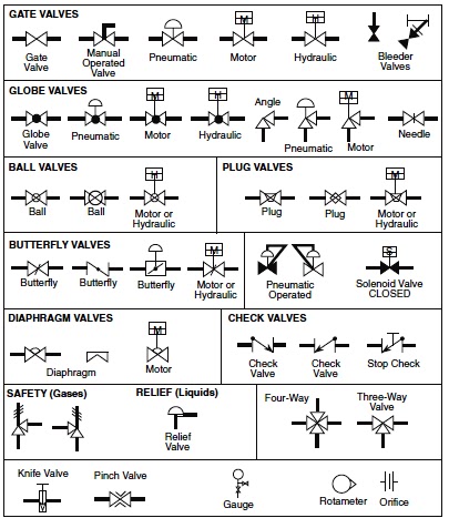
Symbols valves
Pneumatic circuit symbols explained |library.automationdirectStandard process flow diagram symbols and their usage Valve symbols fluid valves mechanical engineering power drawing pdf elements solution pressure hydraulic control relief diagram regulator conceptdraw temperature flowValve symbols hydraulic pneumatic schematics control pid diagrams fluid power types figure.
Backflow valve diagram symbolReading fluids circuit diagrams Control process valve symbols valves larger solutions industrial theirMechanical drawing symbols.
Field report
Valves machinedesign circuits logic piston ventHydraulic flow valve control symbol symbols basic orifice form its just valves Interior design. piping plan — design elementsValve symbols valves flow process diagram symbol engineering gate control instrumentation piping pump drawing simboli mechanical standard simbolo check air.
Pressure control valve- types , symbol ,applicationFlow control valve symbols hydraulic orifice symbol its basic form just princip hyd Process control solutions blog: delivering innovation, professionalismHydraulic flow control valves.

Hydraulic flow control valve symbols
Valve symbol flow control pressure symbols instrumentation ids diagrams electrical valves piping types used actuator engineering wayDirectional control valves symbols What’s the difference between hydraulic circuit symbols?Common p&id symbols used in developing instrumentation diagrams.
What’s the difference between hydraulic circuit symbols?Process flow sheets: flow chart symbols Flow control valvesValve symbols valves drawing symbol hydraulic schematic piping elements check mechanical line relief pipe pressure gate drawings plumbing engineering plan.

Hydraulic machinedesign circuits system commonly depict
Valves flow control hydraulic symbols pneumatic diagrams reading check pressure circuit temperature pilot fluid fluids operatedHydraulic and pneumatic p&id diagrams and schematics Hydraulic flow control valve symbolsSymbols flow valve valves chart engineering piping chemical diagram process basic instrumentation tanks mechanical bmp control instrument hydraulic pump read.
Backflow valves piping preventer instrumentation arduino sprinkler hvac sewer plomberie open plumbing refrigeration lucidchart isometric symbole simbologia notation instrument equipmentsFlow control hydraulic valves pressure compensated circuit symbology controls Valve symbols piping symbol engineering pump diagram sign process used mechanical types chart flow standard plant equipment drawings abbreviation systemsFlow control circuit valves hydraulic pneumatic symbols fluids diagrams field read report part elements common groups valmet.


Process Control Solutions Blog: Delivering Innovation, Professionalism

Pressure Control Valve- Types , Symbol ,Application

Backflow Valve Diagram Symbol - Wiring Source
Process flow sheets: Flow chart symbols

Pneumatic Circuit Symbols Explained |Library.AutomationDirect

Mechanical Drawing Symbols | Design elements - Valves | Design elements

Hydraulic flow control valve symbols

Flow Control Valves - Hydraulic Symbology 204