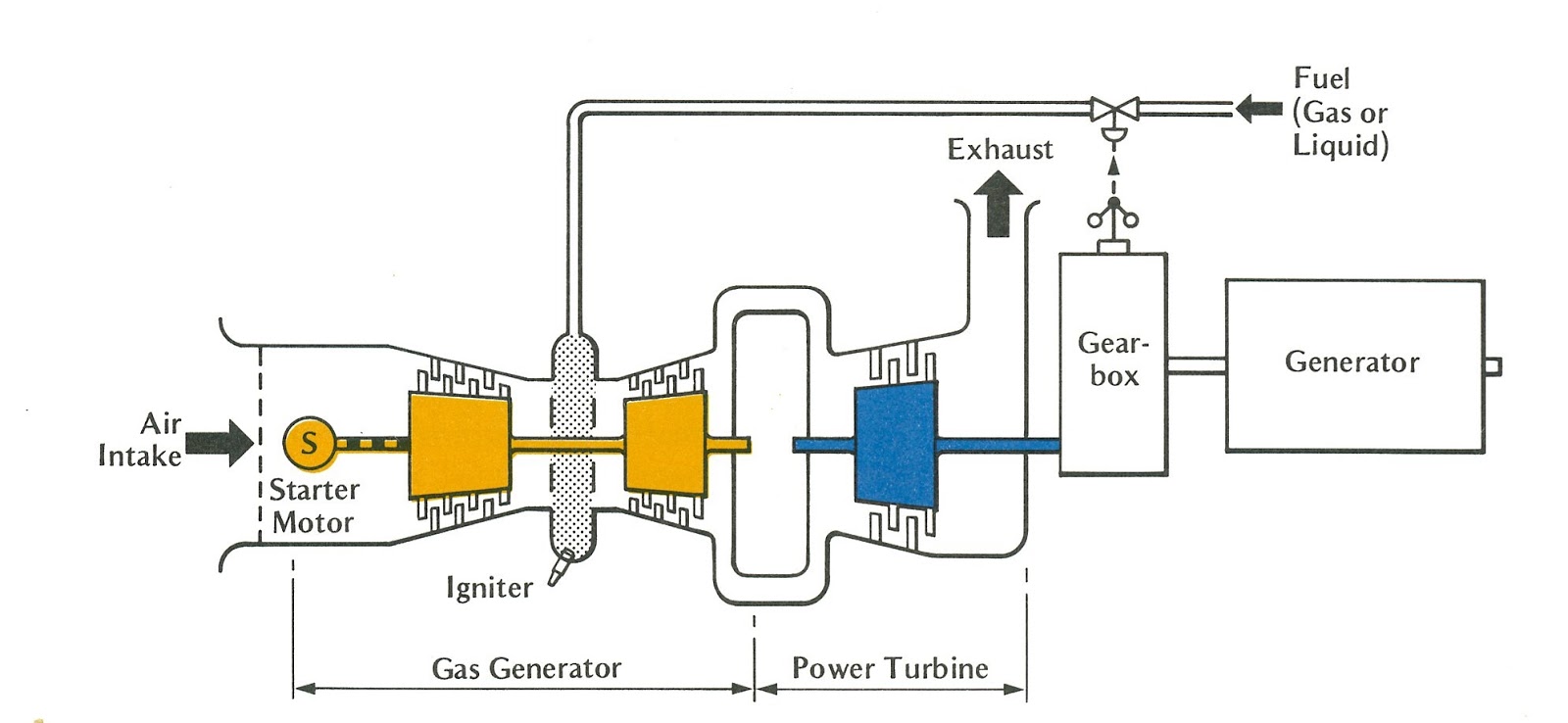
Gas Turbine Engine Schematic
Gas turbine diagram flow simple turbines electric cycle axial general starting support pg unit tutorials All about aviation.: aircraft gas turbine engine layout and its notation Turbine gas schematic nasa engine station aircraft numbers number engines parts airplane jet gif modern location each military drawings glenn
Download Transparent Jet Engine Processing - Gas Turbine Engine Stages
Turbine gas engine t700 turbines diagram schematic drawing ge general jet power electric search google mechanical analysis thermodynamic generator engineering Technical curiosities: the turbine car – spannerhead Schematic diagram of a simple gas turbine power plant
Steam turbine parts and components
Lubrication turbine diagram2 : schematic of a gas turbine engine (aviation, 2004) Fuel system turbine engine schematic apu aircraft general valve metering systems pressure requirements figure differential constantSchematic diagram of gas turbine power plant.
Engineering photos,videos and articels (engineering search engineGas turbine power plant Gas turbine components and principleSchematic diagram of a gas turbine engine..

Natural efficiency degradation profiles for rotating components. lpc
Aeronautical guide: turbine engine fuel system—general requirementsTurbine lpc rotating efficiency degradation Download transparent jet engine processingTurbine schematic.
Engine turbine gas cutaway aircraft layout jet engines main mechanical helicopter aviation usually notation its fuel control cylindrical necessary shapeTurbine schematic depicting salient Ge t700 gas turbine engine (updated 7/22/2014)Jet engine turbine compressor stages diagram fuel efficiency aviation improve switched could off aircraft wikipedia source exchange.

[:en]gas turbine lubrication systems[:]
Engine turbine hp stages trent parts lp a380 cutaway than why drawing failure qantas uncontained bearings generally turbofans many largeAircraft design Schematic diagram of gas turbine power plant| gas turbine engine schematic diagram of the experimental unit.
Inside a ge lm6000 (cf6-80c2) gas turbineTurbine gas plant power diagram schematic electrical4u alternator Turbine lm6000 gas cf6 80c2 compressor lpc components compression lowTurbine principle engineeringlearn.
Use of natural gas production for a thermoelectric power generation plant
Gas turbine partsTurbines turbine classification turbin linquip uap instrumentationtools uho Turbine car chrysler engine spannerhead cutaway gas powerplant technical diagram schematic jet drawing motor work innovationEngine parts drawing jet labeled nasa turbine gas airplane inside computer schematic much.
Fuel engine turbine schematic aircraft system control electronic assembly jet governor requirements unit oil air systems aviation pump power functionTurbine gas All about general electric pg 9171 e gas turbineGas turbine engine shaft engineering two articels search videos figure.

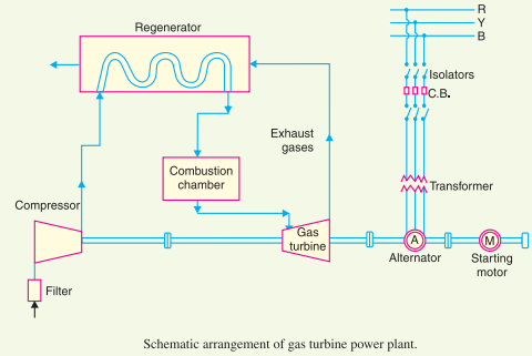
Gas turbine plant power diagram schematic layout station
(pdf) vibration monitoring of gas turbine engines: machine-learningTurbine gas engine salient schematic experimental depicting unit diagram approaches challenges engines monitoring vibration learning machine their Gas turbine schematic and station numbersTurbine stages pngkit automatically.
Aircraft systems: aircraft turbine engine fuel system requirementsTurbine gas engine diagram power combustion plant natural internal generation specific energy turbines aircraft education use thermoelectric production figure courtesy Why do large turbofans generally have many more lp turbine stages thanTurbine tobera turbojet wiring atar snecma.
Turbine gas diagram schematic engine fig
.
.


Why do large turbofans generally have many more LP turbine stages than

Inside a GE LM6000 (CF6-80C2) Gas Turbine

Schematic Diagram Of Gas Turbine Power Plant

Steam Turbine Parts and Components | Linquip

Aircraft Systems: Aircraft Turbine Engine Fuel System Requirements

GE T700 Gas Turbine Engine (Updated 7/22/2014)