Relay Control Board Schematic
8 channel lpt relay board Relay module 5v x 1 relay Schematic diagram relay driver board project
Control the relay using an arduino - Electrical Engineering Stack Exchange
Rs 232 relay control board using pic16f84a Board relay control 232 rs circuit schematic using circuits pic power serial selection mode following order other indicate led which 5v single-channel relay module, pinout diagram
4-channel relay driver circuit and pcb design
Relay module 5v schematic control protosuppliesMiscellaneous projects Relay breakout schematic circuit board pcbRelay arduino board diagram control fan shield schematic wiring channel.
Pic controlled relay driverRelay schematic arduino control using google yielded section edit drive simple file search has Relay module relays in3 connected in2 in4 in1 input pins any digitalEsp8266 nodemcu relay module.

Relay schematic channel module control power circuit optocoupler 5v driver supply circuits relays voltage arduino use opto leds level low
Schematic diagram relay driver board projectRelay control circuit diagram Relay schematic4-channel relay board.
Circuit relayRelay layout Projects relay board miscellaneous schematic miscRelay circuit page 9 : automation circuits :: next.gr.
Relay channel schematic board circuit arduino pcb connection topic electronics lab control output
Relay schematic circuit output electronicBoard relay drawing Relay diagram board breakout circuit settingRelay computer two circuits circuit gr next pc adder schematic.
On the drawing board: relay boardHow to make relay module circuit and pcb and earn money Relay circuit driver channel pcb module diagram board circuits arduino 5v 12v relays layout project ac isolated operate choose projectsRelay module circuit diagram pcb.

Electronic kits, dual relay board
Control the relay using an arduinoRelay esp8266 nodemcu esp32 gpio connecting arduino configuration controlling appliances Relay arduino circuit board shield automation uno diagram project control ethernet schematic module 5v using channel opto 3v isolated gpioNetwork installation.
[diagram] 3 pin horn relay diagram wiring schematic full version hd5-relay module circuit diagram and pcb Lpt powerRelay circuit and breakout board.
8 relay control circuit
Relay circuit earnRelay wiring diagram and function explained Relay circuit control 24vHow to build a control circuit with adjustable working time via wi-fi.
Index [www.rhwebco.com]Relay wiring spst socket 40a fused schematic diode horn mgispeedware prong rocker wires lighted connect mgi accessory Relay module circuitWiring understand principle.

Internet of things : open source home automation project using arduino
Relay schematic esp8266Relay module Relay dual kits schematicRelay board network schematics automation jouko engineer laboratory designed built mr box distance lars server ed.
Relay driver pic controlled schematics schematic 1117 filtering pcb layouts code clickChannel 5v pinout pcb monofindia Pcb designRelay trigger why schematic pcb.

2 channel relay board
.
.


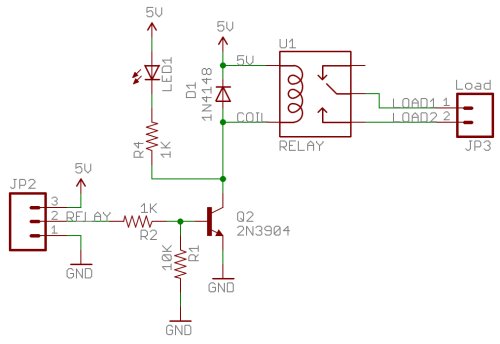
SCHEMATIC DIAGRAM Relay Driver Board Project

Miscellaneous Projects

esp8266 - Feedback schematic/pcb 16 channel relay wifi module

Relay Wiring Diagram and Function Explained - ETechnoG
![[DIAGRAM] 3 Pin Horn Relay Diagram Wiring Schematic FULL Version HD](https://i2.wp.com/mgispeedware.com/wp-content/uploads/2019/05/relay-socket-wiring-diagram-4-pin.jpg)
[DIAGRAM] 3 Pin Horn Relay Diagram Wiring Schematic FULL Version HD